YM2612
| YM2612 | |
 |
|
| Developer: | Yamaha |
| Released: | 198?-??-?? |
| Type: | Chip |
| Channels: | 1.) FM Synthesis |
The YM2612, aka OPN2, is a six-channel sound chip developed by Yamaha. It belongs to Yamaha's OPN family of FM synthesis chips used in several game and computer systems.
Developed as a stripped-down version of the YM2608, it lacks its larger sibling's ADPCM channel, Rhythm Sound System, General Instrument AY-3-8910 components, and GPIO ports. It also includes a simplified sound mixer with integrated DAC. It was also available in CMOS form, as the YM3438, aka OPN2C. It was most notably used in the Sega Mega Drive game console and the FM Towns computer series. As the YM3438, it was used by Sega in various arcade game systems, including the Mega-Play, System 18, and System 32.
The YM2612 has the following features:
- Six concurrent FM channels (voices)
- Four operators per channel
- Two interval timers
- A sine-wave low frequency oscillator
- Analogue stereo output (most other contemporary Yamaha FM chips require a separate external digital-to-analog converter chip)
- For channels 3 and 6, operator frequencies can be set independently, making dissonant harmonics possible. (Normally, they would have a simple relation like e.g. 2× or 3× relative to a common base frequency.)
- Per-channel programmable stereo sound (left, right, or both left and right resulting in centre)
- Patch compatibility with Yamaha DX/TX synthesizers, for example FB-01, |TX81Z, and others, once the user accounts for the differing parameter ranges displayed by the synths as a convenience to the user. This of course does not account for differences such as these synths not offering a sine wave for the LFO, differing clock rates and hence envelope speeds, and some particular sound signatures of the YM2612 as described next.
The major difference between the YM2612 and the YM2608 is the removal of the original accumulator-equipped sound mixer, which mixed together the 14-bit floating point output of the FM channels. Instead it uses a simpler time-division sound multiplexer, which first truncated the 14-bit channel output to 9-bits, then rapidly looped through outputting each channel. Also, the truncation of the output causes a glitch in the negative edge of waveforms, whereby they were shifted out of place, causing a distinctive form of distortion known as the "ladder effect". Post-YM2612 sound filtering circuitry varied in quality between devices using the YM2612, thus affecting the sound quality even further.
Along with the mixer changes, the chip was stripped of its predecessor's SSG component, although its vestigial SSG envelope generator is still functional.
The sixth channel can act as a surrogate PCM channel by means of the 'DAC Enable' register, allowing the chip to play 8-bit PCM sound samples. Enabling the register disables FM output for that channel. PCM data is written to the channel via an 8-bit register. The YM2612 does not provide any timing or buffering of the PCM samples, so all frequency control and buffering must be done in software by the host processor.
The YM3438, aka OPN2C, the CMOS form of the YM2612, changed the Channel 6 DAC output to the same 9-bit output in FM mode. The chip also had higher output impedance, requiring heavier external noise filtering circuitry but outputting louder sound. Sega used an improved version of the OPN2C for the Model 2 version of the Sega Mega Drive, which does not perform the bit-depth truncating seen in the original OPN2 and OPN2C as described above, and as such does not suffer from the "ladder effect".
Pinout
| # | Pin | Function |
|---|---|---|
| 1/12 | GND | Ground Terminals |
| 2–9 | D0 – D7 | 8-bit Bidirectional data bus |
| 10 | NC | Not connected |
| 11 | /IC | System reset, initialize registers, active low |
| 13 | /IRQ | Maskable Interrupt Request, active low |
| 14 | /CS | Chip Select, active low |
| 15 | /WR | Write mode on data bus, active low |
| 16 | /RD | Read mode on data bus, active low |
| 17 | A0 | Read/Write Enable, active high |
| 18 | A1 | Part 1 / Part 2 select (low=1, high=2) |
| 19 | A.GND | Analog Ground Terminal for internal D/A converter |
| 20–21 | MOL, MOR | Analog sound outputs, left and right |
| 22 | A.Vcc | Analog Vcc Terminal for internal D/A converter |
| 23 | Vcc | +5V Power Terminal |
| 24 | øM | Master Clock (7.67 MHz recommended) |

| /CS | /RD | /WR | A0 | A1 | State of Data Bus |
|---|---|---|---|---|---|
| 0 | 1 | 0 | 0 | 0 | Selects Part 1 Register |
| 0 | 1 | 0 | 1 | 0 | Writes data to selected Part 1 Register. |
| 0 | 0 | 1 | 1 | 0 | Reads the status of Part 1. |
| 0 | 1 | 0 | 0 | 1 | Selects Part 2 register |
| 0 | 1 | 0 | 1 | 1 | Writes data to selected Part 2 register. |
| 0 | 0 | 1 | 1 | 1 | Reads the status of Part 2. |
| 1 | × | × | × | × | D0 through D7 become high-impedance. |
Picture Gallery
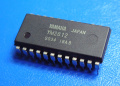
An unattached YM2612.
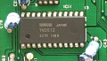
Soldered onto a Mega Drive.

A circuit diagram of the YM2612.

